EMG-Device
Project for university course: Principles of Digital Fabrication of Oulu University
Everything done, everything up to date and project presented.
final presentation: https://docs.google.com/presentation/d/1xxOuLbYDE3mbfAP0H2NyMZXC_jU_autwXX0Ozza_mss/edit?usp=sharing
repository: https://github.com/Demkku/EMG-Device
diary: https://demkku.github.io/EMG-Device/
Summary report
click here to download the summary report PDF with pictures and links Note! link only available when browsing github pages and the link doesn’t seem to work with Edge Browser
Our final concept was to measure heart rate using voltage sensors that have been amplified and filtered using operational amplifiers. Then the heart rate peak is detected with Arduino and the time difference between the peaks is measured and converted for a servo. Then the servo moves a needle on a measuring table to display the heart rate.
Our project consists of 4 elements: a circuit board and a case for it, a measuring table and software to read sensor data and convert into readable data and software to control a servo for the measuring table.
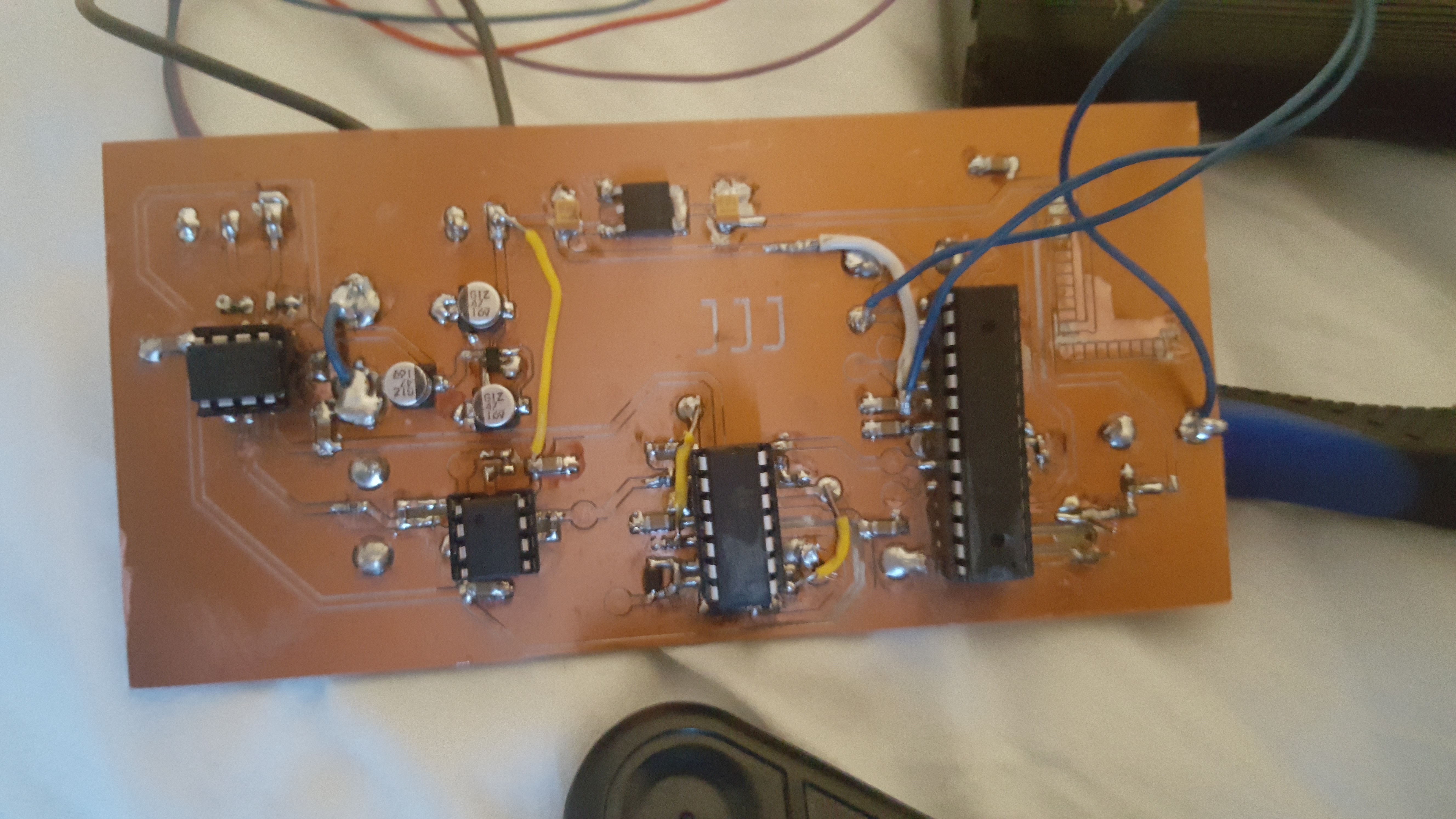
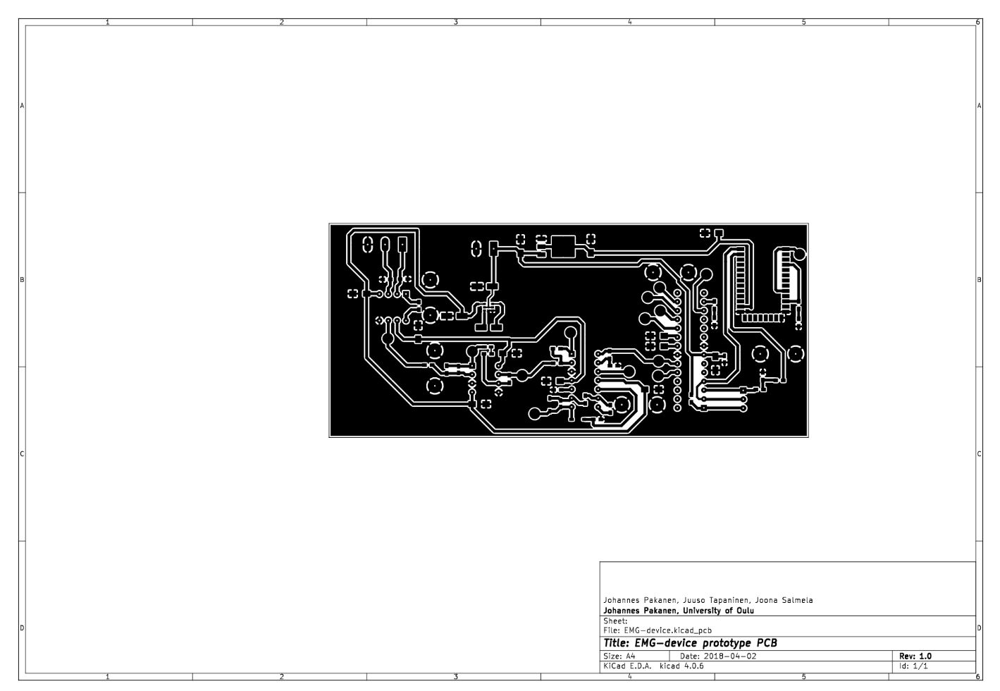
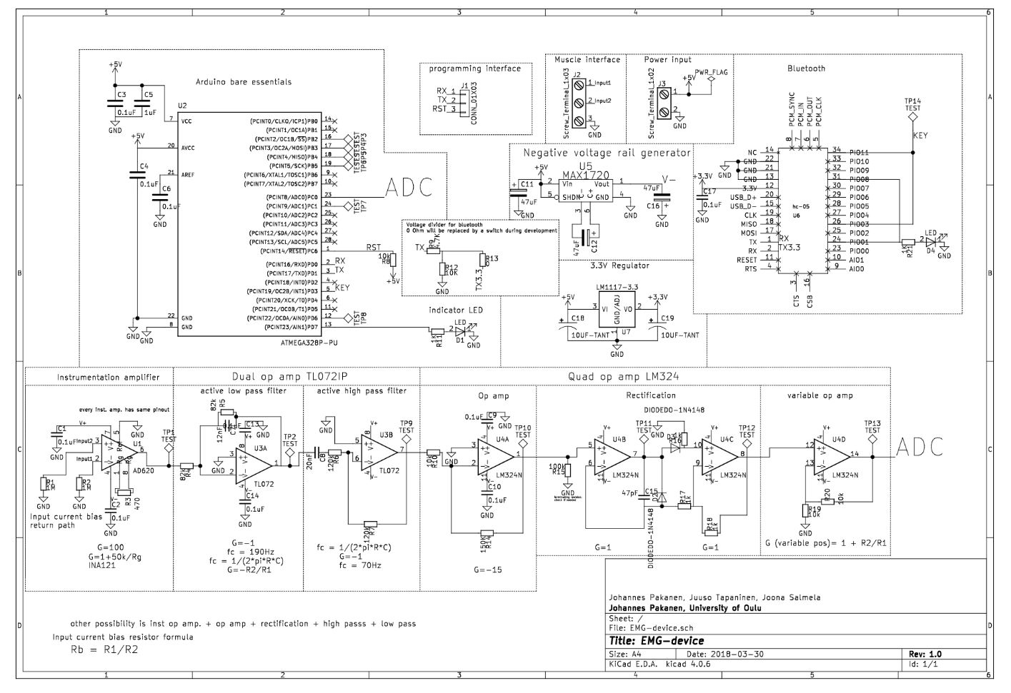
Johannes designed the circuit board using KiCad. Voltage -sensors didn’t have strong enough signal, so in order to use it properly the signal had to be amplified and filtered using operational amplifiers. The voltage difference in the order of 1mV is measured across the chest with EKG electrodes, +, - and ground. The signal to an instrumental operational amplifier, where common mode noise is rejected, and the signal is amplified. Next, the signal goes through low and high pass filters. After filtering is further amplification and full wave rectification. Last, one more amplifier and then the signal goes to the ADC of ATMEGA328p.
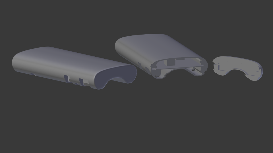
The case was designed by using Blender. Blender isn’t quite the best software in designing real life objects, but to create a simple and aesthetically nice case wasn’t a problem. The case was designed around the project images exported from Kicad. Some approximation by eye had to be made with components and they were pretty much correct. Only the size of the PCB would have gone terribly wrong if only the Kicad images were followed. The case was finally printed with Fortus 380mc printer. The result was fair, only the bottom was so thin that it cracked a little.
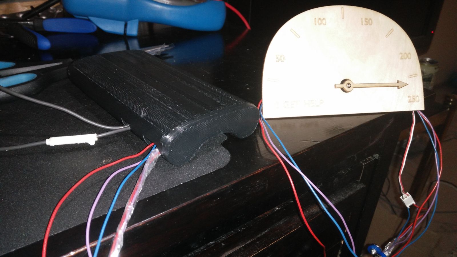
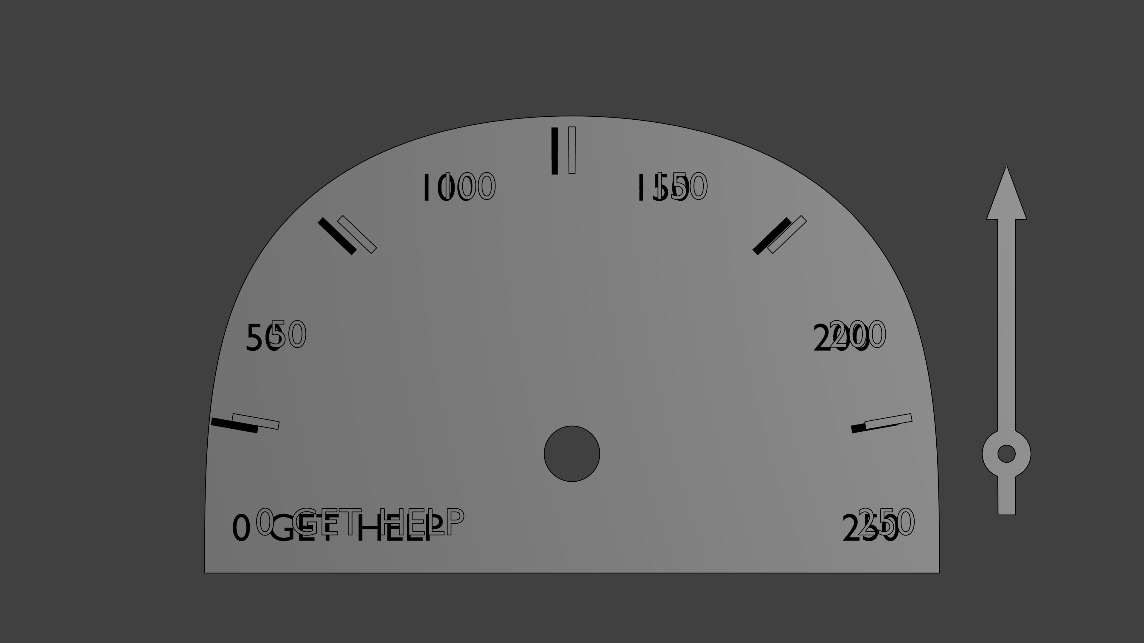
The measuring table was designed with Blender, from which the vector file was imported to Inkscape. From Inkscape the vector file was exported as a pdf and then printed using a laser cutter out of plywood. The first cut table was too thick, and the servo couldn’t be put through. The arrow needed a hole for the screw, too. That’s why the table was cut again, and it turned out without problems. The servo was glued on the backside of the table.
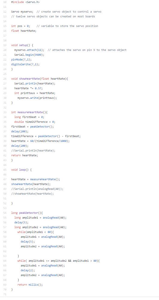
The software was done on Arduino IDE platform. We programmed our code to ATMEGA328p microcontroller using Arduino UNO. The programs purpose was to measure the time difference between every heartbeat and calculate how many times the heart beats in a minute. EKG -sensors had a triangle wave that measured voltage of the heartbeat and it had some noise in it. To get reliable data we had to calculate the time difference between every peak of the voltage signal and not take the noise into account. We made the program to measure only the rising side of the wave and its maximum voltage. That way we got the most reliable data. Then we had to program a correct angle to a servo to display the heartrate on a measuring table.
Lessons learned
We learned a lot in this project. We learned to use different software like KiCad, Blender, GitHub and Inkscape. We learned that one should always make a second version of the hardware design if any problems would rise. We learned how to use operational amplifiers in practice and how to compare different components to get the best one for its use. We also learned to watch carefully that everything gets correctly imported other software like all of our parts in the circuit board design didn’t get correctly imported to the drilling machine because we used KiCad as our design system.
We learned a good lesson in time management. It would be a lot better to divide the work of the project to entire period so there wouldn’t be such a rush at the end of the period to get everything done.
Our recommendation to others doing the same project is to take your time designing every element of the project carefully so everything goes smoothly when you start building up the project. This project can be a bit difficult so it would be better done in your on pace and not in an introductory course like Principles of digital fabrication.
Feedback to course responsibles
The course was nice. It was good change for our usual courses that are heavily theoretic besed. It helped us to learn new things to designour projects so the course was also quite usefull.
W19
On monday the case is printed, also project software created and completed as it is very simple. The case slightly cracked during removal from the printer.
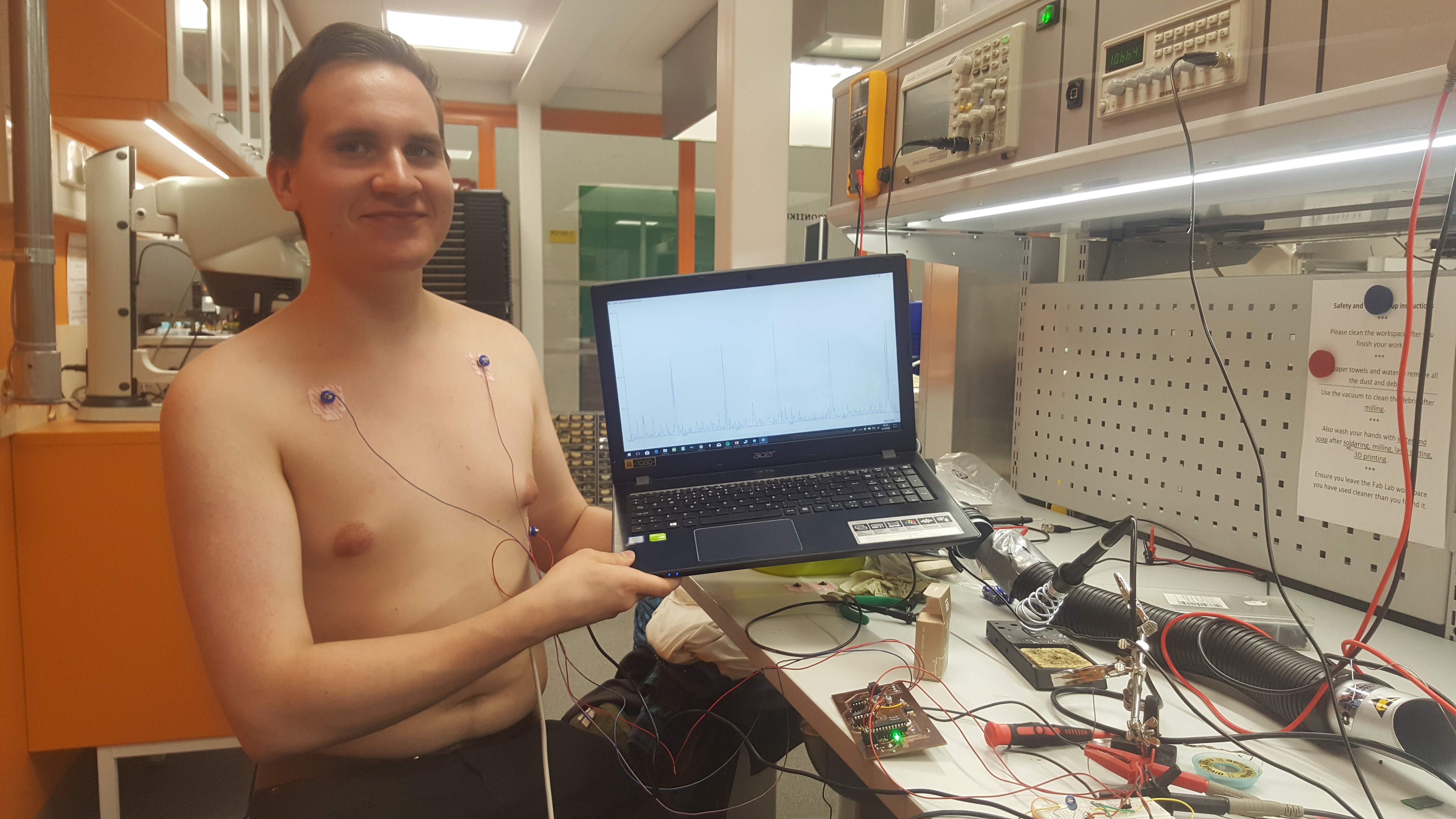
With the completetion of SW with Aruino IDE and receiving of the mesuring electrodes on the last minute PROJECT COMPLETED!!!
the complete project:
testing after pads finally received:
The code:
W18
Testing software created. Extensive testing and simulation done. See baseband testing report and oscilloscope pictures.
final output to ADC on simulation, massive hf noise:
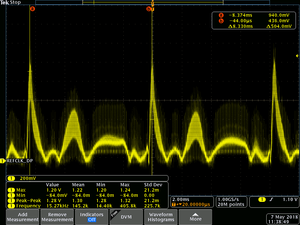
Component values changed and filtering added
W17
The remaining components soldered and measurements taken to the case. During the soldering, some missing traces noticed, but fixed with jump wires. Traces missing on the layout.
EKG electrodes ordered from Medkit.
Modeling of the case started with blender. Also, modeling of the measuring table started with blender.
W16
Midterm meeting
Later on the week, components received and first soldered.
W15
The idea maybe changed to a heart rate sensor, which can be measured with the same circuit. Will be tested when components received, probably on W16 or 17
V2 board Milled with Success!!!
On the left first try, on the right the V2 board

Components ordered from Mouser.
Design for an enclosure started, will be 3D printed.
W14
Layout V1 started and completed:
BOM completed.
V1 board milled. The board failed with board width at 0.4mm and uneven board at milling machine. As a result wire width doubled to 0.8mm wherever possible.
W13
After brainstorming requrements set
Kicad schematics started:
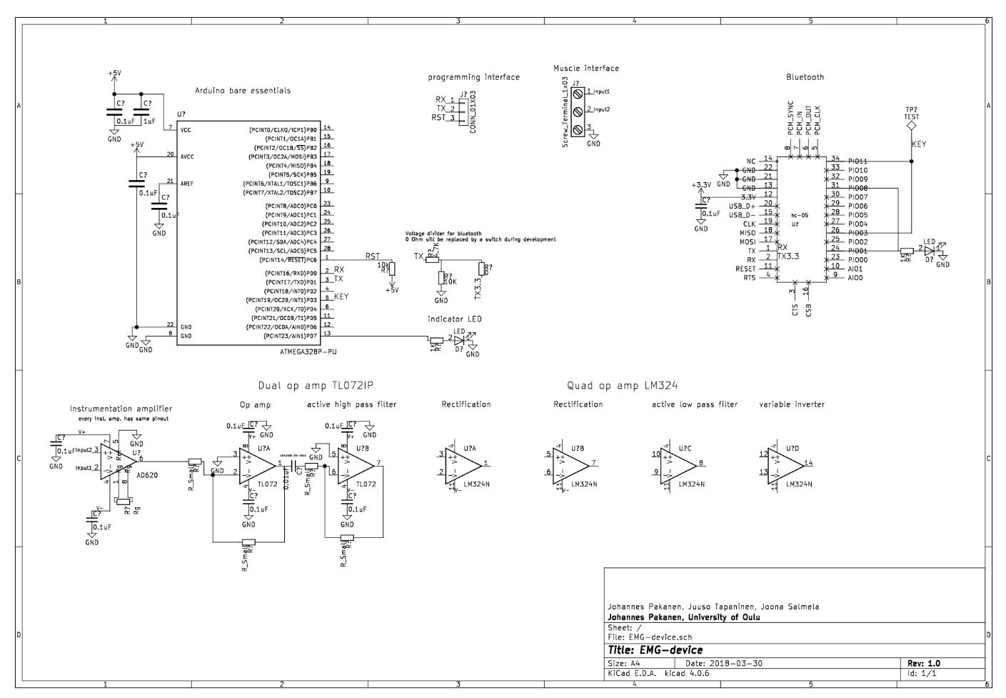
Kicad schematics done after a lot of reading about op amps:
W12
The repositery and site created
Start of the project:
Introductory report, EMG-Device
521159P Principles of Digital Fabrication DIGIFAB10
The idea is to build a device that can measure EMG signal. EMG signals are created when muscles are used, and nerve impulses are sent. Impulses create a potential difference in the order of 1-10mV which is amplified, filtered and read with an Arduino. To meet course requirements an enclosure will be 3D printed and something laser cut. We arrived at the idea of an EMG device as a combination interest to the subject of bio signals, the challenge and courses about op amps are running in parallel with this course, so we can use in practice what we have learned.
Other project that we thought of was an Arduino tank that could locate WIFI signal sources, but this would have been very software heavy, and because we are EE students, we wanted to put emphasis on hardware. Also locating sources turns out to be very hard. Our back up plan is an EKG device, which instead of 3 measuring lanes, uses only one.
BOM: QTY Component type Package Source Price(eur) URL
10 0.1uF capacitor 1206 Electronics club 0
1 1uF capacitor 0603 Johannes 0
1 12nF capacitor 0603 Johannes 0
1 20nF capacitor 0603 Johannes 0
3 47uF capacitor 5x5mm Johannes 0
1 47pF capacitor 0603 Johannes 0
2 10uF tant. Cap. 1206? Electronics club 0
2 SMD LED 0603 Johannes 0
2 1N4148W-F, SMD diode SOD-123 Mouser 0,3 https://www.mouser.fi/ProductDetail/Diodes-Incorporated/1N4148W-7-F?qs=sGAEpiMZZMvilazpv%252bFqvbevgE8TPEOt
1 3 pin header male 100mil header Electronics club 0
1 3 screw terminal 5mm terminal Johannes 0
1 2 screw terminal 5mm terminal Johannes 0
2 1MOhm resistor 0603? Electronics club/Johannes 0
1 470 Ohm resistor 0603 Johannes 0
2 82kOhm resistor 0603 Johannes 0
2 120kOhm resistor 0603 Johannes 0
5 10kOhm resistor 0603 Johannes 0
1 4,7kOhm resistor 0603 Johannes 0
5 1kOhm resistor 0603 Johannes 0
1 0 Ohm resistor 0603 Johannes 0
1 15kOhm resistor 0603 Johannes 0
1 100kOhm resistor 0603 Johannes 0
2 DIP8 socket DIP8 Johannes 0
1 DIP14 socket DIP14 Johannes 0
1 DIP28 socket DIP28 Johannes 0
1 MAX1720 charge pump TSOP-6 Mouser 0,58 https://www.mouser.fi/ProductDetail/ON-Semiconductor/MAX1720EUTG?qs=sGAEpiMZZMtitjHzVIkrqdfdkrf0Qy0Qzg%252b1DRXikVE%3d
1 HC-05 BT unit custom Johannes 0
1 INA121PA inst. amp. DIP8 Mouser 4,94 https://www.mouser.fi/ProductDetail/Texas-Instruments/INA121PA?qs=sGAEpiMZZMsE1dKaA2ImUPh%2fgv48%2feoeALcGDSe487k%3d
1 TL072IP op. Amp. DIP8 Mouser 0,56 https://www.mouser.fi/ProductDetail/Texas-Instruments/TL072IP?qs=5BZzbFV4k2v7IBrcArRPQw==
1 LM324N DIP14 Mouser 0,43 https://www.mouser.fi/ProductDetail/Texas-Instruments/LM324N?qs=sGAEpiMZZMtCHixnSjNA6Araa3jp4DVB37ZJv3RooEc%3d
1 ATMega 328p DIP28 Electronics club 0
1 LM1117 3.3V regulator TO252 Electronics club 0
8 button things button Johannes 0
50 Electrodes, 34mm button Medkit.fi 14,26 https://www.medkit.fi/ambu-blue-sensor-m-oo-s?___store=finland&nosto=frontpage-nosto-1
Welcome to GitHub Pages
You can use the editor on GitHub to maintain and preview the content for your website in Markdown files.
Whenever you commit to this repository, GitHub Pages will run Jekyll to rebuild the pages in your site, from the content in your Markdown files.
Markdown
Markdown is a lightweight and easy-to-use syntax for styling your writing. It includes conventions for
Syntax highlighted code block
# Header 1
## Header 2
### Header 3
- Bulleted
- List
1. Numbered
2. List
**Bold** and _Italic_ and `Code` text
[Link](url) and 
For more details see GitHub Flavored Markdown.
Jekyll Themes
Your Pages site will use the layout and styles from the Jekyll theme you have selected in your repository settings. The name of this theme is saved in the Jekyll _config.yml configuration file.
Support or Contact
Having trouble with Pages? Check out our documentation or contact support and we’ll help you sort it out.